-
Notifications
You must be signed in to change notification settings - Fork 333
Part 1: understandable raytracing
This is another chapter from my brief course of lectures on computer graphics. This time we are talking about the ray tracing. As usual, I try to avoid third-party libraries, as I believe that it makes students check what's happenning under the hood. Also check the tinykaboom project.
There are plenty of raytracing articles on the web; however the problem is that almost all of them show finished software that can be quite difficult to understand. Take, for example, the very famous businness card ray tracer challenge. It produces very impressive programs, but it's very difficult to understand how this works. Rather than showing that I can do renders, I want to tell you in detail how you can do it by yourself.
Note: It makes no sense just to look at my code, nor just to read this article with a cup of tea in hand. This article is designed for you to take up the keyboard and implement your own rendering engine. It will surely be better than mine. At the very least change the programming language!
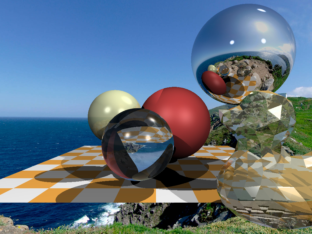
So, the goal for today is to learn how to render such images:

#include <limits>
#include <cmath>
#include <iostream>
#include <fstream>
#include <vector>
#include "geometry.h"

void render() {
    const int width    = 1024;
    const int height   = 768;
    std::vector<Vec3f> framebuffer(width*height);

    for (size_t j = 0; j<height; j++) {
        for (size_t i = 0; i<width; i++) {
            framebuffer[i+j*width] = Vec3f(j/float(height),i/float(width), 0);
        }
    }

    std::ofstream ofs; // save the framebuffer to file
    ofs.open("./out.ppm");
    ofs << "P6\n" << width << " " << height << "\n255\n";
    for (size_t i = 0; i < height*width; ++i) {
        for (size_t j = 0; j<3; j++) {
            ofs << (char)(255 * std::max(0.f, std::min(1.f, framebuffer[i][j])));
        }
    }
    ofs.close();
}

int main() {
    render();
    return 0;
}
Only render() is called in the main function and nothing else. What is inside the render() function? First of all, I define the framebuffer as a one-dimensional array of Vec3f values, those are simple three-dimensional vectors that give us (r,g,b) values for each pixel. The class of vectors lives in the file geometry.h, I will not describe it here: it is really a trivial manipulation of two and three-dimensional vectors (addition, subtraction, assignment, multiplication by a scalar, scalar product).
I save the image in the ppm format. It is the easiest way to save images, though not always the most convenient way to view them further. If you want to save in other formats, I recommend that you link a third-party library, such as stb. This is a great library: you just need to include one header file stb_image_write.h in the project, and it will allow you to save images in most popular formats.
Warning: my code is full of bugs, I fix them in the upstream, but older commits are affected. Check this issue.
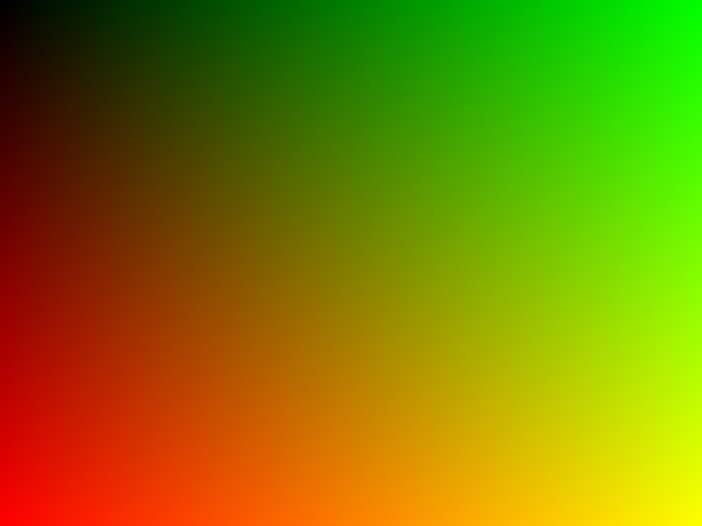
So, the goal of this step is to make sure that we can a) create an image in memory + assign different colors and b) save the result to disk. Then you can view it in a third-party software. Here is the result:
 This is the most important and difficult step of the whole chain. I want to define one sphere in my code and draw it without being obsessed with materials or lighting. This is how our result should look like:

For the sake of convenience, I have one commit per step in my repository; Github makes it very easy to view the changes made. Here, for instance, what was changed by the second commit.
To begin with, what do we need to represent the sphere in the computer's memory? Four numbers are enough: a three-dimensional vector for the center of the sphere and a scalar describing the radius:
struct Sphere {
    Vec3f center;
    float radius;

    Sphere(const Vec3f &c, const float &r) : center(c), radius(r) {}

    bool ray_intersect(const Vec3f &orig, const Vec3f &dir, float &t0) const {
        Vec3f L = center - orig;
        float tca = L*dir;
        float d2 = L*L - tca*tca;
        if (d2 > radius*radius) return false;
        float thc = sqrtf(radius*radius - d2);
        t0       = tca - thc;
        float t1 = tca + thc;
        if (t0 < 0) t0 = t1;
        if (t0 < 0) return false;
        return true;
    }
};
The only non-trivial thing in this code is a function that allows you to check if a given ray (originating from orig in the direction of dir) intersects with our sphere. A detailed description of the algorithm for the ray-sphere intersection can be found here, I highly recommend you to do this and check my code.
How does the ray tracing work? It is pretty simple. At the first step we just filled the picture with a gradient of colors:
    for (size_t j = 0; j<height; j++) {
        for (size_t i = 0; i<width; i++) {
            framebuffer[i+j*width] = Vec3f(j/float(height),i/float(width), 0);
        }
    }
Now for each pixel we will form a ray coming from the origin and passing through our pixel, and then check if this ray intersects with the sphere:
If there is no intersection with sphere we draw the pixel with color1, otherwise with color2:
Vec3f cast_ray(const Vec3f &orig, const Vec3f &dir, const Sphere &sphere) {
    float sphere_dist = std::numeric_limits<float>::max();
    if (!sphere.ray_intersect(orig, dir, sphere_dist)) {
        return Vec3f(0.2, 0.7, 0.8); // background color
    }
    return Vec3f(0.4, 0.4, 0.3);
}

void render(const Sphere &sphere) {
	[...]
    for (size_t j = 0; j<height; j++) {
        for (size_t i = 0; i<width; i++) {
            float x =  (2*(i + 0.5)/(float)width  - 1)*tan(fov/2.)*width/(float)height;
            float y = -(2*(j + 0.5)/(float)height - 1)*tan(fov/2.);
            Vec3f dir = Vec3f(x, y, -1).normalize();
            framebuffer[i+j*width] = cast_ray(Vec3f(0,0,0), dir, sphere);
        }
    }
	[...]
}
At this point, I recommend you to take a pencil and check on paper all the calculations (the ray-sphere intersection and the sweeping of the picture with the rays). Just in case, our camera is determined by the following things:
- picture width
- picture height
- field of view angle
- camera location, Vec3f(0.0.0)
- view direction, along the z-axis, in the direction of minus infinity
Let me illustrate how we compute the initial direction of the ray to trace. In the main loop we have this formula:
            float x =  (2*(i + 0.5)/(float)width  - 1)*tan(fov/2.)*width/(float)height;
            float y = -(2*(j + 0.5)/(float)height - 1)*tan(fov/2.);
Where it comes from? Pretty simple. Our camera is placed in the origin and it faces the -z direction. Let me illustrate the stuff, this image shows the camera from the top, the y axis points out of the screen:

As i said, the camera is placed at the origin, and the scene is projected at the screen that lies in the plane z = -1. The field of view specifies what sector of the space will be visible at the screen. In our image the screen is 16 pixels wide; can you compute its length in world coordinates? It is pretty simple: let us focus on the triangle formed by the red, gray and gray dashed line. It is easy to see that tan(field of view / 2) = (screen width) * 0.5 / (screen-camera distance). We placed the screen at the distance of 1 from the camera, thus (screen width) = 2 * tan(field of view / 2).
Now let us say that we want to cast a vector through the center of the 12th pixel of the screen, i.e. we want to compute the blue vector. How can we do that? What is the distance from the left of the screen to the tip of the blue vector? First of all, it is 12+0.5 pixels. We know that 16 pixels of the screen correspond to 2 * tan(fov/2) world units. Thus, tip of the vector is located at (12+0.5)/16 * 2*tan(fov/2) world units from the left edge, or at the distance of (12+0.5) * 2/16 * tan(fov/2) - tan(fov/2) from the intersection between the screen and the -z axis. Add the screen aspect ratio to the computations and you will find exactly the formulas for the ray direction.
The hardest part is over, and now our path is clear. If we know how to draw one sphere, it will not take us long to add few more. Check the changes in the code, and this is the resulting image: The image is perfect in all aspects, except for the lack of light. Throughout the rest of the article we will talk about lighting. Let's add few point light sources:
struct Light {
    Light(const Vec3f &p, const float &i) : position(p), intensity(i) {}
    Vec3f position;
    float intensity;
};
Computing real global illumination is a very, very difficult task, so like everyone else, we will trick the eye by drawing completely non-physical, but visually plausible results. To start with: why is it cold in winter and hot in summer? Because the heating of the Earth's surface depends on the angle of incidence of the Sun's rays. The higher the sun rises above the horizon, the brighter the surface is. Conversely, the lower it is above the horizon, the dimmer it is. And after the sun sets over the horizon, photons don't even reach us at all.
Back our spheres: we emit a ray from the camera (no relation to photons!) at it stops at a sphere. How do we know the intensity of the intersection point illumination? In fact, it suffices to check the angle between a normal vector in this point and the vector describing a direction of light. The smaller the angle, the better the surface is illuminated. Recall that the scalar product between two vectors a and b is equal to product of norms of vectors times the cosine of the angle between the vectors: a*b = |a| |b| cos(alpha(a,b)). If we take vectors of unit length, the dot product will give us the intensity of surface illumination.
Thus, in the cast_ray function, instead of a constant color we will return the color taking into account the light sources:
Vec3f cast_ray(const Vec3f &orig, const Vec3f &dir, const Sphere &sphere) {
    [...]
    float diffuse_light_intensity = 0;
    for (size_t i=0; i<lights.size(); i++) {
        Vec3f light_dir      = (lights[i].position - point).normalize();
        diffuse_light_intensity  += lights[i].intensity * std::max(0.f, light_dir*N);
    }
    return material.diffuse_color * diffuse_light_intensity;
}
The modifications w.r.t the previous step are available here, and here is the result:
 The dot product trick gives a good approximation of the illumination of matt surfaces, in the literature it is called diffuse illumination. What should we do if we want to draw shiny surfaces? I want to get a picture like this:

Check how few modifications were necessary. In short, the brighter the light on the shiny surfaces, the less the angle between the view direction and the direction of reflected light.
This trickery with illumination of matt and shiny surfaces is known as Phong reflection model. The wiki has a fairly detailed description of this lighting model. It can be nice to read it side-by-side with the source code. Here is the key picture to understanding the magic:

Mere six lines of code allow us to achieve this: when drawing each point, we just make sure that the segment between the current point and the light source does not intersect the objects of our scene. If there is an intersection, we skip the current light source. There is only a small subtlety: I perturb the point by moving it in the direction of normal:
Vec3f shadow_orig = light_dir*N < 0 ? point - N*1e-3 : point + N*1e-3;Why is that? It's just that our point lies on the surface of the object, and (except for the question of numerical errors) any ray from this point will intersect the object itself.
It's incredible, but to add reflections to our render, we just need to add three lines of code: Vec3f reflect_dir = reflect(dir, N).normalize();
Vec3f reflect_orig = reflect_dir*N < 0 ? point - N*1e-3 : point + N*1e-3; // offset the original point to avoid occlusion by the object itself
Vec3f reflect_color = cast_ray(reflect_orig, reflect_dir, spheres, lights, depth + 1);See it for yourself: when intersecting the sphere, we just compute the reflected ray (with the aid of the same function we used for specular highlights!) and recursively call the cast_ray function in the direction of the reflected ray. Be sure to play with the recursion depth, I set it to 4, try different values starging from 0, what will change in the picture? Here is my result with reflections and a recursion depth of 4:

 Till this moment we rendered only spheres because it is one of the simplest nontrivial mathematical objects. Let us add a plane. The chessboard is a classic choice. For this purpose, it is quite enough to add a dozen lines.
And here is the result:

As promised, the code has 256 lines of code, check it for yourself!
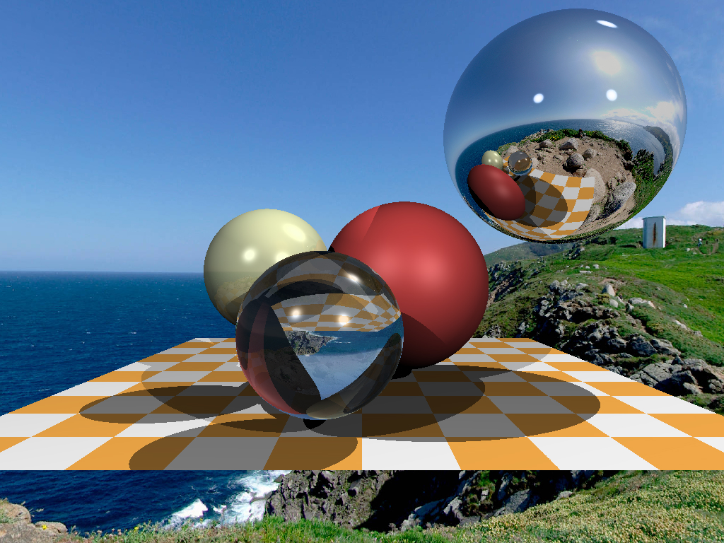
We've come a long way: we've learned how to add objects to a scene, how to compute rather complicated lighting. Let me leave you two assignments as homework. Absolutely all the preparatory work has already been done in the branch homework_assignment. Each assignment will require ten lines of code tops. At the moment, if the ray does not intersect any object, we just set the pixel to the constant background color. And why, actually, is it constant? Let's take a spherical photo (file envmap.jpg) and use it as a background! To make life easier, I linked our project with the stb library for the convenience of working with the jpg format. It should give us such an image: We can render both spheres and planes (see the checkerboard). So let's draw triangle meshes! I've written a code that allows you to read an .obj file, and I've added a ray-triangle intersection function to it. Now adding the duck to our scene should be quite trivial:
 My main goal is to show projects that are interesting (and easy!) to program. I am convinced that to become a good programmer one must do lots of side projects. I don't know about you, but I personally am not attracted to accounting software and the minesweeper game, even if the complexity of the code is quite comparable.
Few hours and two hundred and fifty lines of code give us a raytracer. Five hundred lines of the software rasterizer can be done in a few days. Graphics is really cool for learning the programming!
